Table of Contents
Introduction
In this post I’m going to talk about real time video processing using the MAX10 Arrow Deca development board. I will talk about the different parts of the project such as the HDMI Driver, the convolution engine and the RGB to Gray converter.
Field-programmable gate arrays (FPGAs) are an excellent choice for video processing due to their high performance, low latency, flexibility, and the ability to perform multiple tasks in parallel. The FPGA I have on my development board is the MAX10 FPGA from Intel.
One of the key algorithms I wanted to implement is the convolution, which is a fundamental operation in image and video processing. Convolution involves taking a small matrix called a kernel and applying it to an image or video frame. This operation is used for a wide range of applications, including edge detection, blurring, and noise reduction. At the time of writing, I have only tested the edge detection, but I think it can do most of the effects.
When thinking about the project, I wanted the dataflow to look something like the following figure. Unfortunately I was not able to make the camera module work, so the project does not have a camera. Instead there is a generated pattern, and the convolution is applied to this pattern.

The dataflow of the current project looks more or less like that, even if technically, the HDMI driver is with the pattern generator, and the signals are being delayed by the convolution engine.

HDMI Driver
I started by writing the HDMI Driver. This is important because I cannot see the result of the convolution without a display. I also need to check that the displayed pixels are in the correct position.
To send data to the screen, I’m going to use the HDMI TX connector present on the development board. The HDMI is controlled by a transmitter chip that translates VGA style data to HDMI data. This chip is the ADV7513 from Analog Devices(datasheet and User Manual). It is a High Performance HDMI Transmitter capable of supporting all video formats up to 1080p.
Getting the timings informations
Driving a display with VGA only requires 2 counters to keep track of where we are in the frame, 3 control signals (Data Enable, Horizontal Sync, Vertical Sync) and the RGB data. Each resolution needs different timings for the control signals, and a different pixel clock frequency.
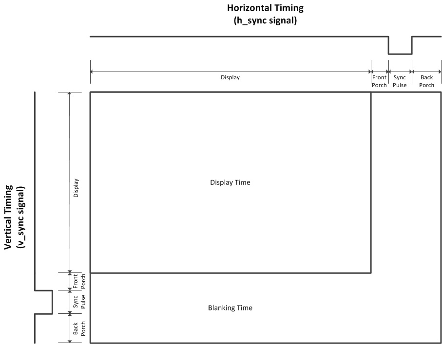
The figure below shows how the vertical and horizontal sync signals are used. In this figure, the polarity of the signals (vsync and hsync) is active low. It means the signal is low during the sync pulse. For some standard, the signals can be active high. The polarity is specified in the calculator listed below.
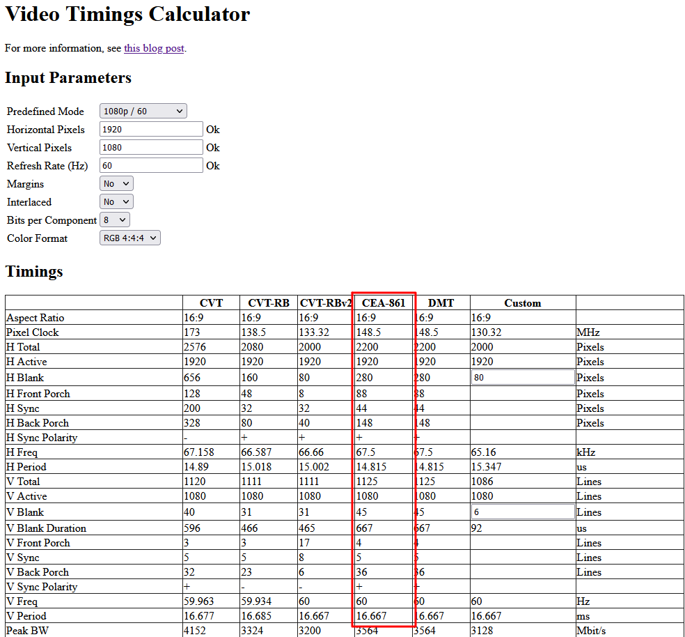
To find the correct timings, I used this Video Timings Calculator. The website let’s you select any resolution and refresh rate, and it will give you all the informations needed (see the generic in the entity). In the example below, I choose a 1080p resolution with a 60Hz refresh rate. The information that we need are in the column CEA-861.
VHDL implementation
The HDMI transmitter has to be configured using I2C. The code is not covered here, because I did not write it. It came in an example projet with the dev board. It contains a clock divider to generate the SCL, a FSM to decided when to start and stop the initialisation, and an LUT containing the registers address and the data that needs to be written in it. You can find the code in the src/HDMI folder in the Github repository.
In the table taken from the Video Timings Calculator, the pixel clock for a 1080p resolution was 148.5 MHz. To achieve this, I used a PLL IP and configured it to get the correct output frequency.
The entity of the HDMI driver is represented by the following VHDL code. The default values in the generic are for a resolution of 1080p @ 60Hz.
entity HDMI_TX is
	generic (
		h_total: 	integer := 2200;
		h_front: 	integer :=   88;
		h_sync: 	integer :=   44;
		h_back: 	integer :=  148;
		h_active: 	integer := 1920;

		v_total: 	integer := 1125;
		v_front: 	integer :=    4;
		v_sync: 	integer :=    5;
		v_back: 	integer :=   36;
		v_active: 	integer := 1080
	);

	port (
		clk:		in		std_logic;
		rst_n:		in		std_logic;
		de:			out		std_logic;
		vs:			out		std_logic;
		hs:			out		std_logic;
		r:			out		std_logic_vector(7 downto 0);
		g:			out		std_logic_vector(7 downto 0);
		b:			out		std_logic_vector(7 downto 0)
	);
end HDMI_TX;
The architecture of the controller is made of 3 processes. One for the vertical sync, one for the horizontal sync and one for the data. When testing the driver, the data was either a full color or some random patterns based on the value of the counters.
architecture behavioral of HDMI_TX is

	signal h_count: integer 	:= 0;
	signal v_count: integer 	:= 0;

	signal h_act:	std_logic 	:= '0';
	signal v_act:	std_logic 	:= '0';

begin

	-- VGA controls

	h_ctrl: process(clk)
	begin
		if rising_edge(clk) then
			if rst_n = '0' then
				h_count <= 0;
				hs <= '0';
				h_act <= '0';
			else

				-- Counter
				if h_count = (h_total - 1) then
					h_count <= 0;
				else
					h_count <= h_count + 1;
				end if;

				-- sync and active signals handler
				if h_count < h_active then
					h_act <= '1';
					hs <= '0';
				elsif h_count < (h_active + h_front) then
					h_act <= '0';
					hs <= '0';
				elsif h_count < (h_active + h_front + h_sync) then
					h_act <= '0';
					hs <= '1';
				else
					h_act <= '0';
					hs <= '0';
				end if;

			end if;
		end if;
	end process; -- end h_ctrl


	v_ctrl: process(clk)
	begin
		if rising_edge(clk) then
			if rst_n = '0' then
				v_count <= 0;
				vs <= '0';
				v_act <= '0';
			else

				-- Counter
				if h_count = (h_total - 1) then
					if v_count = (v_total - 1) then
						v_count <= 0;
					else
						v_count <= v_count + 1;
					end if;
				end if;

				-- sync and active signals handler
				if v_count < v_active then
					v_act <= '1';
					vs <= '0';
				elsif v_count < (v_active + v_front) then
					v_act <= '0';
					vs <= '0';
				elsif v_count < (v_active + v_front + v_sync) then
					v_act <= '0';
					vs <= '1';
				else
					v_act <= '0';
					vs <= '0';
				end if;

			end if;
		end if;
	end process; -- end v_ctrl


	frame_gen: process(clk)
	begin
		if rising_edge(clk) then
			if h_act = '1' and v_act = '1' then
				de <= '1';
				r <= std_logic_vector(to_unsigned(h_count, 12))(9 downto 2);
				g <= std_logic_vector(to_unsigned(v_count, 12))(9 downto 2);
				b <= std_logic_vector(to_unsigned(h_count, 12))(9 downto 2);
			else
				de <= '0';
				r <= (others => '0');
				g <= (others => '0');
				b <= (others => '0');
			end if;
		end if;
	end process; -- end frame_gen

end behavioral ; -- behavioral
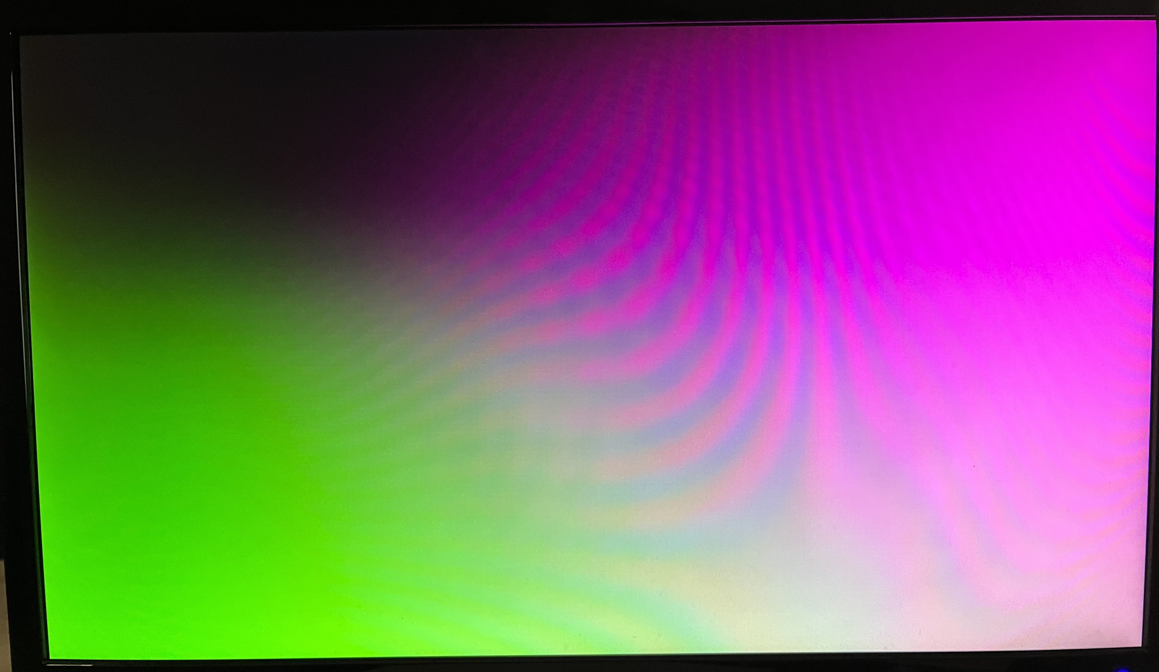
When connecting a display to the board, I could see the expected results, so I concluded the driver was working as intended. This is the result of the test.
RGB to grayscale converter
I decided to convert the RGB video stream coming from the camera (pattern generator) to a grayscale stream. There are two reasons to this.
- I don’t need the colors when doing edge detections (with the Sobel or Laplacian kernel).
- There are less data to handle when using grayscale.
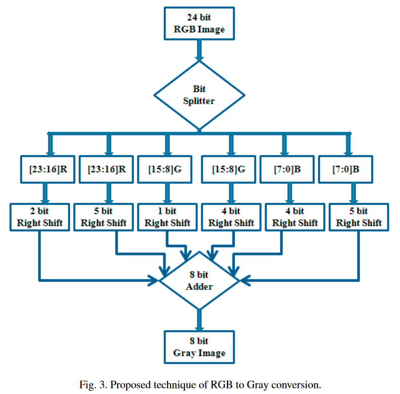
To do the conversion, I searched for an efficient way to convert RGB to Grayscale on FPGA. I found this paper, and decided to implement it. They explain in the paper that the gray value of a pixel is composed of 28.1% of red, 56.2% of green and 9.3% of blue, this is used in the “rgb2gray” function in MATLAB.
NOTE
After testing the grayscale conversion, I decided that the blue was not high enough, and added more blue by shifting by 2 bits intead of 4.
This is the block diagram of the proposed technique.
VHDL Implementation
library ieee;
use ieee.std_logic_1164.all;
use ieee.numeric_std.all;

entity rgbgray is
	port (
		r:			in		std_logic_vector(7 downto 0);
		g:			in		std_logic_vector(7 downto 0);
		b:			in		std_logic_vector(7 downto 0);

		gray:		out		std_logic_vector(7 downto 0)
	);
end rgbgray;

architecture rtl of rgbgray is

	signal r1: std_logic_vector(7 downto 0);
	signal r2: std_logic_vector(7 downto 0);
	signal g1: std_logic_vector(7 downto 0);
	signal g2: std_logic_vector(7 downto 0);
	signal b1: std_logic_vector(7 downto 0);
	signal b2: std_logic_vector(7 downto 0);

begin

	r1 <= "00" 		& r(7 downto 2); -- shift right by 2
	r2 <= "00000" 	& r(7 downto 5); -- shift right by 5
	g1 <= "0" 		& g(7 downto 1); -- shift right by 1
	g2 <= "0000" 	& g(7 downto 4); -- shift right by 4
	b1 <= "00" 		& b(7 downto 2); -- shift right by 2
	b2 <= "00000" 	& b(7 downto 5); -- shift right by 5

	-- Add all the values together
	gray <= std_logic_vector(unsigned(r1) + unsigned(r2) + unsigned(g1) + unsigned(g2) + unsigned(b1) + unsigned(b2));

end rtl;
Simulating the design
To verify that I implemented correctly the design, I simulated it with ghdl, and checked the waveform using GTKWave. I wrote a very basic testbench and tested the conversion. In the paper they give an example conversion with the following values :
- R :
b11010110 - G :
b11111110 - B :
b01011100
They also give the intermediate R1 and R2 values (values after shifting the bits). The result of this conversion is : b11010000.
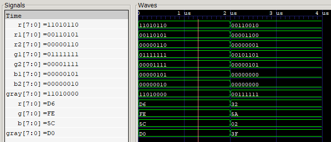
We can see in the simulation that I have the same result as the one in the example given in the paper. I also tested another value and verified it by doing the calculations by hand using python.
NOTE
The tests were done before adding more blue.
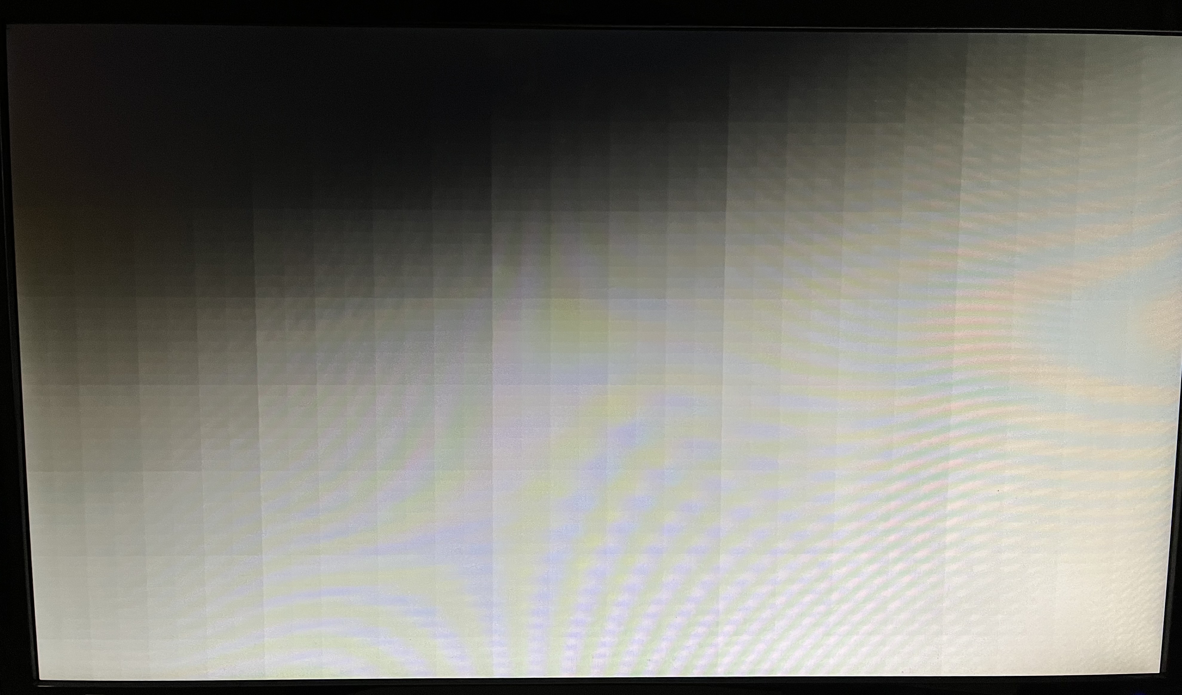
At this point, I could display anything on a screen using the HDMI Driver. I could also feed the data through the grayscale converter and see the result on the screen. This is the same pattern than the one generated to test the HDMI but converted to grayscale through the converter :
Convolution engine
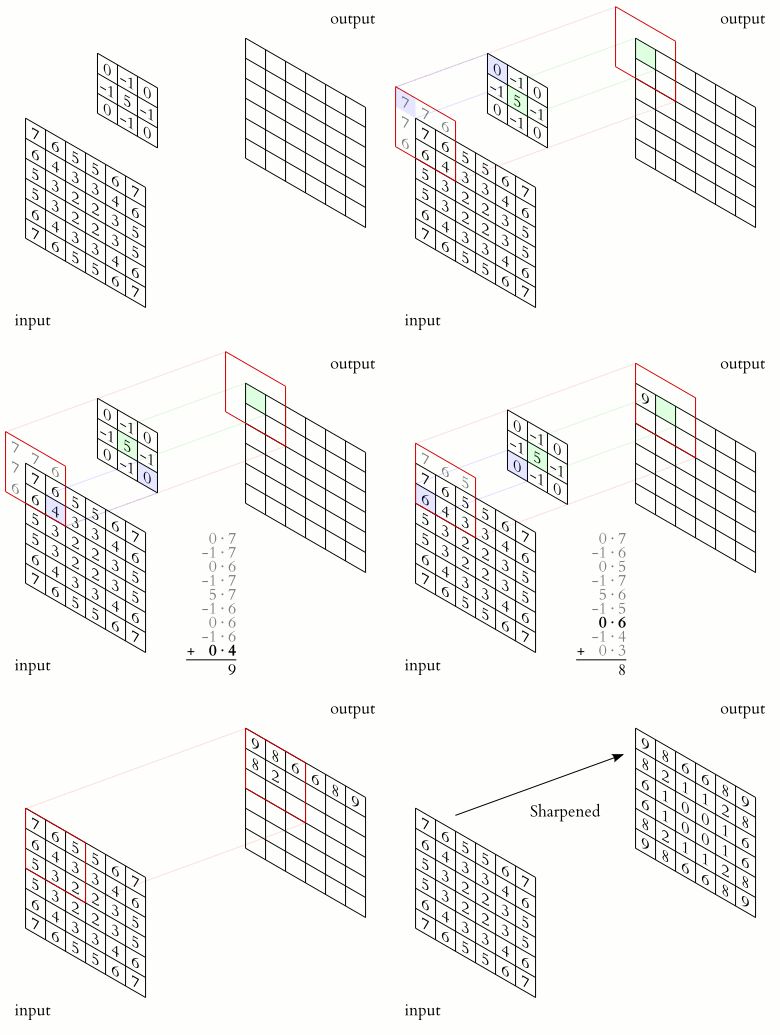
As mentioned in the introduction, the convolution is a very important algorithm in image processing. The gif shows how a kernel is applied on a matrix (the grayscale image). Different kernels are used to obtain different results such as : edge detection, noise filtering, blur effect.
2D Convolution in python
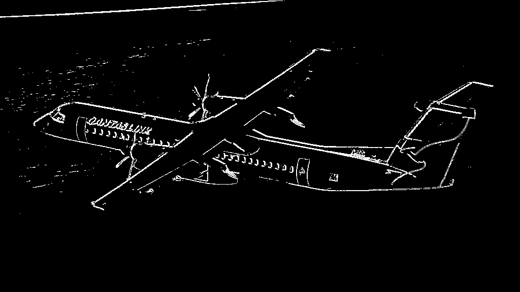
The kernel used in the previous gif can be used to sharpen an image. I have tested this sharpening kernel in python on an image, I also tested a sobel filter (edge detection) on the same image. Here are the python code and the results.
import cv2
import numpy as np

plane = cv2.imread("plane.jpg", 0)

kernel = np.array([ [ 0, -1,  0],
					[-1,  5, -1],
					[ 0, -1,  0]])

plane_sharp = cv2.filter2D(plane, -1, kernel=kernel)

plane_sobel_x = cv2.Sobel(plane, -1, 1, 0)
plane_sobel_y = cv2.Sobel(plane, -1, 0, 1)
plane_sobel = ((plane_sobel_x + plane_sobel_y) > 64) * 255

cv2.imwrite("plane_sharp.jpg", plane_sharp)
cv2.imwrite("planel_sobel.jpg", plane_sobel)
The pictures are presented in the following order : the original, the sharpened and the edge detected with the sobel filter.


2D Convolution in VHDL
I started by designing the convolution engine as a schematic on draw.io. The gif below is an animation of a kernel being applied to an image. At every clock cycle, a new pixel comes in, and every pixels are shifted by one.
Because the kernel is applied to pixels on the line above and under the current pixel, I used a FIFO to keep the pixels in memory. The size of the FIFO is really important, because for the convolution to work, the pixels have to be multiplied by the right kernel coefficient at the right time. A wrong size will result in a wrong timing.
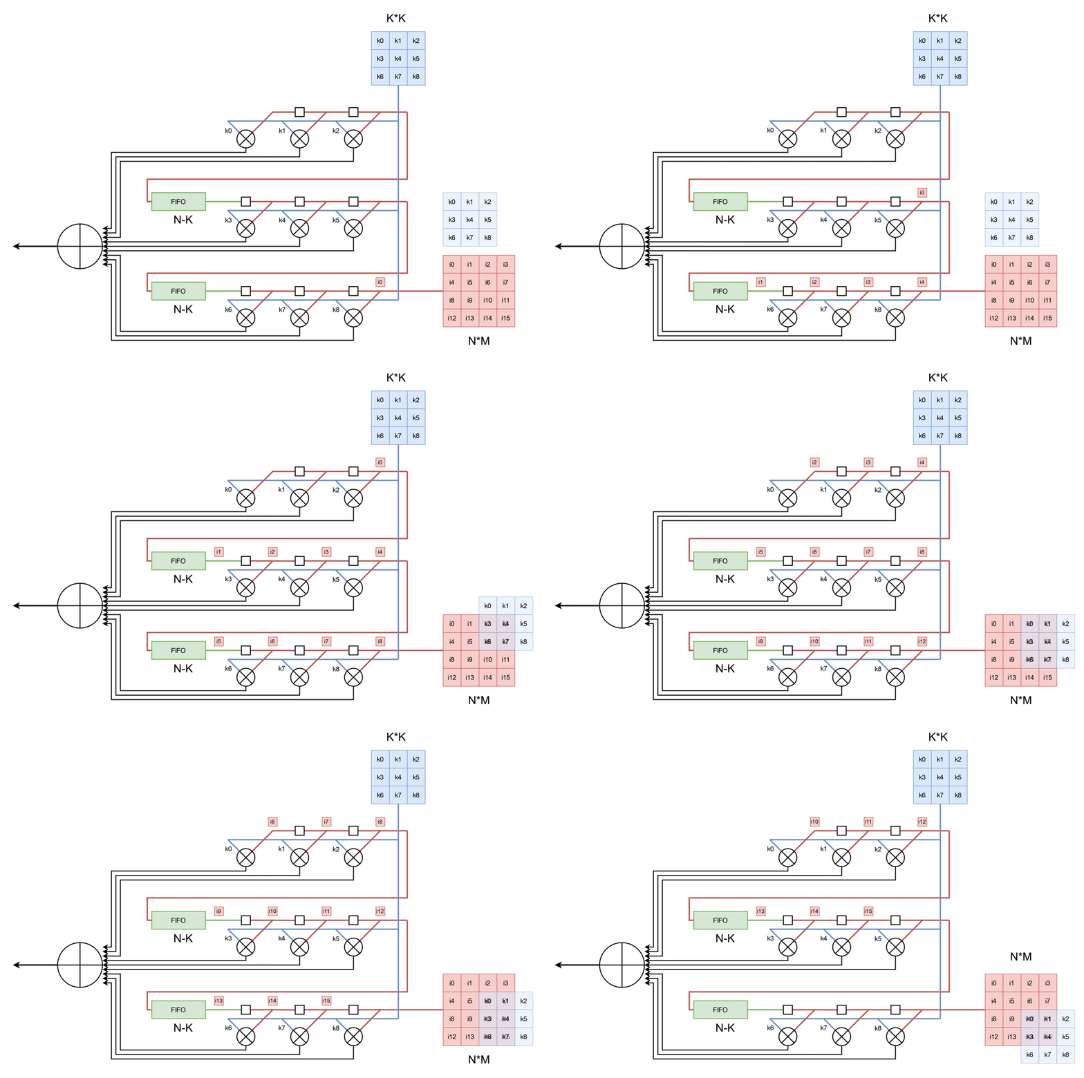
We can observe a delay before the kernel is applied to the first pixel, but after the delay there is a new (filtered) pixel going out at every clock cycle. Because of this delay, I also added 3 shift registers to delay the hsync, vsync and de control signals.
WARNING
I am 90% certain there is a bug in the current code. It looks like it’s working but I think it’s not because of the delay
The entity of the engine is the following :
entity convolution is
	port (
		clk:		in		std_logic;
		pxl:		in		std_logic_vector(7 downto 0);
		de_in:		in		std_logic;
		hs_in:		in		std_logic;
		vs_in:		in		std_logic;

		new_pxl:	out		std_logic_vector(7 downto 0) := (others => '0');
		gray_out:	out		std_logic_vector(7 downto 0) := (others => '0');
		de_out:		out		std_logic := '0';
		hs_out:		out		std_logic := '0';
		vs_out:		out		std_logic := '0'
	);
end convolution;
We can see the control signals coming in, and the delayed control signals going out. The input pixel is also delayed and can be displayed at the same time as the filtered output if you need to.
Here is the architecture of the engine for an edge detection using a sobel filter :
architecture rtl of convolution is

	constant FRAME_WIDTH:	integer := 640;
	constant KERNEL_SIZE:	integer := 3;

	type t_kernel is array (0 to (KERNEL_SIZE*KERNEL_SIZE)-1) of integer;
	type t_fifo is array (0 to FRAME_WIDTH - KERNEL_SIZE - 1) of integer range 0 to 255;

	constant sobel_x: t_kernel := (	-1,  0,  1,
									-2,  0,  2,
									-1,  0,  1);

	constant sobel_y: t_kernel := (	 1,  2,  1,
									 0,  0,  0,
									-1, -2, -1);

	signal new_pxl_x:	integer := 0;
	signal new_pxl_y:	integer := 0;
	signal new_pxl_sum:	integer := 0;

	signal fifo_1:		t_fifo;
	signal fifo_2:		t_fifo;

	signal image: 		t_kernel := (0, 0, 0, 0, 0, 0, 0, 0, 0);

	-- Shift registers to delay the control signals
	constant SR_SIZE:	integer := 5;
	type t_fifo_delay is array (0 to SR_SIZE) of integer range 0 to 255;
	signal fifo_gray:	t_fifo_delay;
	signal de_sr:		std_logic_vector(SR_SIZE downto 0) := (others => '0');
	signal hs_sr:		std_logic_vector(SR_SIZE downto 0) := (others => '0');
	signal vs_sr:		std_logic_vector(SR_SIZE downto 0) := (others => '0');

begin

	de_out <= de_sr(de_sr'high);
	hs_out <= hs_sr(hs_sr'high);
	vs_out <= vs_sr(vs_sr'high);
	gray_out <= std_logic_vector(to_unsigned(fifo_gray(fifo_gray'high), 8));

	shifter: process( clk )
	begin
		if rising_edge(clk) then
			if de_in = '1' then
				image(0) 	<= image(1);
				image(1) 	<= image(2);
				image(2) 	<= fifo_2(fifo_2'high);
				fifo_2 		<= image(3) & fifo_2(0 to fifo_2'high-1);
				image(3) 	<= image(4);
				image(4) 	<= image(5);
				image(5) 	<= fifo_1(fifo_1'high);
				fifo_1 		<= image(6) & fifo_1(0 to fifo_1'high-1);
				image(6) 	<= image(7);
				image(7) 	<= image(8);
				image(8) 	<= to_integer(unsigned(pxl));
				fifo_gray	<= to_integer(unsigned(pxl)) & fifo_gray(0 to fifo_gray'high-1);
			end if;

			de_sr 		<= de_sr(de_sr'high-1 downto 0) & de_in;
			hs_sr 		<= hs_sr(hs_sr'high-1 downto 0) & hs_in;
			vs_sr 		<= vs_sr(vs_sr'high-1 downto 0) & vs_in;

		end if;
	end process; -- shifter

	mutliplier : process( clk )
	begin
		if rising_edge(clk) then

			new_pxl_x <= 	(image(0) * sobel_x(0)) +
							(image(1) * sobel_x(1)) +
							(image(2) * sobel_x(2)) +
							(image(3) * sobel_x(3)) +
							(image(4) * sobel_x(4)) +
							(image(5) * sobel_x(5)) +
							(image(6) * sobel_x(6)) +
							(image(7) * sobel_x(7)) +
							(image(8) * sobel_x(8));

			new_pxl_y <= 	(image(0) * sobel_y(0)) +
							(image(1) * sobel_y(1)) +
							(image(2) * sobel_y(2)) +
							(image(3) * sobel_y(3)) +
							(image(4) * sobel_y(4)) +
							(image(5) * sobel_y(5)) +
							(image(6) * sobel_y(6)) +
							(image(7) * sobel_y(7)) +
							(image(8) * sobel_y(8));

			new_pxl_sum <= abs(new_pxl_x + new_pxl_y);

			if new_pxl_sum > 64 then
				new_pxl <= (others => '1');
			else
				new_pxl <= (others => '0');
			end if;

		end if;
	end process ; -- mutliplier

end rtl;
The file and it’s testbench can be found in the Github repository in the folder src/convolution.
Result
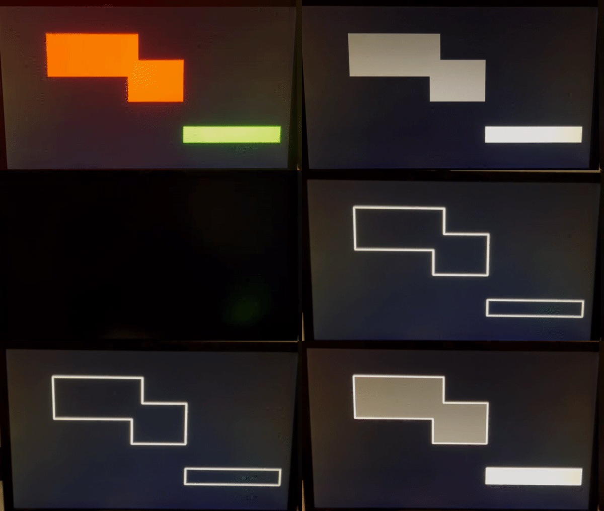
This is the result of the convolution. The video starts by displaying the original pattern, then the grayscale conversion. After a small black screen, there is the result of the convolution with the sobel filter, and finaly the white squares filled with gray is the result of the convolution with the delayed grayscale pixels added.
Conclusion
In this post, I’ve covered most part of my video processing project. The only parts that were not covered are the camera module and the frame buffer. Unfortunately could not make the camera module work, so I decided to drop it and use a static pattern instead. Even if these were not working, I am still happy about the result.
If I could find a VGA Input module, I could use it and place the convolution engine between the vga input and a vga output module. This would let me do some video processing at a resolution of 1080p with a refresh rate of 60Hz.